Sunday 28 March 2021

Home Brew Controller - 15th March - Project Aims and initial parts list

I'm aware that many things like the BrewPi exist, but I didn't want to overcomplicate things and use a Raspberry Pi plus extra hardware. I just wanted something simple that didn't include all the extras like heater/chiller and pump control (as I don't have all these things yet, just a few buckets and boilers)!


Primary Aim:

  • Monitor the temperature of 
    • water/wort during a sparge
    • wort when cooling (after a boil)
    • wort when fermenting
  • locally (on an LCD screen)
  • remote via a web interface over WiFi (potentially with graphing) so I don't have to go out and check on it from time to time)

Secondary Aims:

  • Control things based on temperatures (so I don't have to go out to the garage to turn switches on/off)
    • The boiler (turn it off automatically after the 1-2 hour boil after hopping)
    • brewbelt (to keep the wort warm during fermentation in the winter)


Hardware (Parts list):

I already had most of these parts from previous electronics projects:
  • 1x Nodemcu
  • 1x DHT22
  • 2x DS18B20 temperatue probes (on 3m cables)
  • 1x LCD display 16x2 characters
  • 4x Analog resistor ladder switches
  • 1x 433Mhz RF transmitter (for mains sockets, safer and cheaper than wiring up my own mains relays for boilers)


Software

For circuit/breadboard diagrams I will probably be using fritzing. Recently they started charging a small fee for compiled downloads to support development, but you can still download and install it for free on a mac using homebrew 😁 (pun not intentional) with the command brew install --cask fritzing


For diagrams, I will probably be using this nodemcu part

https://github.com/roman-minyaylov/fritzing-parts/tree/master/esp8266-nodemcu-v3


And I found some good code for controlling the LCD menu

https://majicdesigns.github.io/MD_Menu/ and https://github.com/MajicDesigns/MD_Menu

Along with a library to read the switch inputs

https://github.com/MajicDesigns/MD_UISwitch https://majicdesigns.github.io/MD_UISwitch/class_m_d___u_i_switch___analog.html


I almost used this library https://tsibrov.blogspot.com/2020/09/LiquidCrystal-I2C-Menu.html but found the translated instructions a bit hard to understand.


Alternatively, I could just use BrewPiLess, but what would be the point in that?!

https://github.com/vitotai/BrewPiLess/blob/master/doc/HardwareGeneral.md

https://www.primetimebrewers.com/post/piless-brewpi

Sunday 21 March 2021

Homebrew Controller (for controlling and monitoring my beer brewing in my garage)

It's been a long time since I've updated this blog (almost 5 years) and as you can see from the lack of posts most of the smarthome ideas I originally had haven't actually happened! Mostly through laziness, but more recently because my 1.5 year old daughter has been taking up most of my free time (in a good way).

But, I'm now getting 2-3 hours a day on weekends when my daughter and wife are napping, which is perfect time to add some content and finish off a project I've imagined for a while.... a custom beer brewing controller!

I started a prototype of this a year ago (in the summer of 2020) and over the last few months I've been randomly ordering extra parts and planning how to take this off the breadboard and finish it off. I'll try to document the progress on this blog with weekly updates. I've got a few weeks worth of posts written as drafts, but I should get caught up at some point soon and then I can post realtime progress as I go.


My next post will contain a bit more technical detail of what I've got so far, what it does, and what I want it to do when finished, but for now here are 2 photos while I tidy up the mess of my most recent soldering session.


This is the breadboard prototype that I've been using in 2020:


It's hard to make out the screen, but it displays the garage temperature and humitidy (using a DHT22 sensor) and shows two (A and B) waterproof probe temperatures. It has a web interface that I can access from my LAN to display the same temperature data.


And this is it on my desk next to the enclosure I bought for a few quid off ebay that I want to move it all into once the project is finished.


Sunday 20 November 2016

British Gas - Hive Active Lights Review

My DIY attempts at home automation haven't progressed very far. In January I wired up 2 NodeMCU based ESP8266 Temperature/Humidity sensors which report their statistics via MQTT to my raspberry pi. But I forgot to set up logging to record the sensor data, so the sensors have been announcing temperature and humidity every minute for the last 10 months, and the raspberry pi has been listening and then forgetting it!

However, a few weeks ago I got back into the Home Automation game. When I did my annual switch to a cheaper energy supplier (thanks to Martin Lewis's Cheap Energy Club) I got a free gift for Joining British Gas: Hive Smart Light Bulbs!


I'd already been researching Phillips Hue lightbulbs, but these Hive ones were free. Buying these new would cost around £118, so why not give them a go!

Installing the Hive Hub


This was relatively easy. I already had a spare ethernet port on my home network, and a power socket nearby. The Hive Hub uses what appears to be a standard 500mA USB charger (like you'd find on a cheap android smartphone) but with a propitiatory USB to DC jack cable. It may be possible to power the Hive Hub from a spare USB port, which some home routers have nowadays, but I didn't want to risk it.

I plugged in the cables and a few minutes later I had a blinking status light, which according to the getting started guide meant it had connected to the internet, updated it's firmware, and was ready to search for devices.


Installing the Hive smartphone app guides you through registering the Hub, and linking it's unique activation code (on the back of the hub) to your account. This was pretty straightforward and I could see the Hub in the smartphone app within a few minutes. According to British Gas this activation process can only happen once with a new hub, and secondhand hubs can't be reused. Also, to change the email address on your account you need to phone customer services. It feels like a lot of the basic management and functionality of the Hive Hub and the customer account is immature, but this may improve over time.

The most common use for the Hive Hub is to connect the Home Heating thermostat control to the internet, but I only had 2 smart light bulbs to connect.

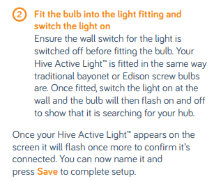
Adding the Smart Lights

Again, the instructions were very basic.


The FAQs on the hive website didn't have any extra help or troubleshooting steps, just "follow the install instructions". I tried multiple times but still nothing. The bulbs no longer flashed when turned on, so I assumed they were sulking and no longer in "pairing mode". Normally, when pairing 2 wireless devices together, there is some sort of "sync" button or similar to re-start the pairing process, but with a light bulb with no buttons this appeared impossible.

So, I gave in and emailed their customer support. I expected to wait a day or 2 for a reply, so started searching for answers. Eventually I found on an amazon Q and A page for the active lights an answer that said:
"We had the same issue and we contacted Hive who advised us to put the light in the unit and switch it on and off 6-7 times thus resetting the bulb."
I tried this, and it worked! The exact process I followed to manually pair the lights to the hub was:

  1. From the mobile app, or web interface, choose the "find new devices" option to start pairing.
  2. Turn the light bulb off with the light switch, count to at least 1 second, then switch it back on.
  3. Repeat this off...wait...on sequence at least 6 times, and the bulb will appear on the "add device" screen of the Hive webpage or smartphone app.
  4. Name your bulb, and if you want to add another, repeat the above steps.

Controlling the Smart Lights

Obviously, you can't turn the lights off at the lightswitch anymore, otherwise they wouldn't be smart! Luckily when turned on at the switch they default to ON, so if you don't have your smartphone you can turn the lightswitch off and on to turn on the light.

But, you're meant to use the app. The UI is a bit rubbish. You can't move items around on the "honeycomb" layout.


Turning lights OFF and ON is easy, and you can dim them in 5% increments.


You can also set daily schedules for the lights to turn on and off, or to a certain brightness.


This is limited to a maximum of 6 changes a day, and they can only occur every 15 minutes (on the our, 15, 30 or 45 mins after it).

For now, I have the lights in my living room (where I spend the most time). They are scheduled to turn on first thing in the morning before I go to work, and again in the evenings before I come home.

It's nice to be able to dim them when watching a film, without getting up to use the physical light switches, but there is no 3rd party integration with other platforms. This is a shame as their competitor Philips has opened their Hue platform to work with things like the Logitech Harmony Hub (which I have) and there are loads of 3rd party apps for Hue (including pebble smartwatch apps).

Summary

The hub setup, while fiddly, is pretty straightforward. For non-technical people the simple instructions are fine, but for those wanting to fix setup problems without phoning or emailing customer support the instructions aren't terribly useful.

The active lights are a pain to "pair" and setup, and aren't very flexible, but once setup and put onto a schedule they do exactly what they're meant to. Software updates in the future may improve the ways the lights can be controlled (e.g. IFTTT support).

The hive mobile app and web interface isn't great, but it can always be updated and improved. Opening up the APIs (via IFTTT or something similar) will allow better integration with other platforms, otherwise you're tied into the relatively limited hive ecosystem.


Next Steps

There are other hive products available: Door/window and motion sensors, switchable mains plugs, RGB multicolour lights, and of course the original home heating thermostat control.

As the 2nd Generation thermostat has recently been released, a lot of the simpler looking 1st Generation thermostats are being sold as people upgrade. I've ordered a second hand thermostat and receiver off eBay. Hopefully these can be added to my existing hub, giving me more functionality!
I'll write another review on this as soon as I've got it installed and used it for a few weeks.

And hopefully there will be ways to integrate all of this with other systems (including my home-made temperature/humidity sensors) so I can slowly build up a smart home without being tied to a specific proprietary platform!

Monday 25 January 2016

Completed ESP8266/NodeMCU temperature and humidity sensor

Credit where credits due, I have taken a lot of inspiration (and borrowed some LUA code) from this blog: https://odd-one-out.serek.eu/esp8266-nodemcu-dht22-custom-modules-firmware/

Anyway, the prototype has been stable for over a week happily posting MQTT messages every minute with temperature and humidity readings. I've got nothing permanent logging or displaying MQTT at the moment, but that's another project in itself :-)

Time to tidy it up and put it in an enclosure. The one I had in mind was £4.09 from maplin and seemed big enough to fit the NodeMCU board and a small USB phone charger. Everything will be contained in one unit that plugs into the wall. The micro USB port for the NodeMCU board will sit near the top so I can re-flash and diagnose issues with it mounted inside the enclosure. I also bought some veroboard/stripboard and heatshrink for tidying wires up with.

First of all, I installed Fritzing (an awesome piece of software) so I could make some nice plans to work from instead of the messy breadboard of parts and wires that was running the prototype. There is an option in Fritzing to create printed PCB layouts, but I won't bother with that unless I mass produce more than a few of these.

Breadboard layout
Nice and simple. There is one DHT22 sensor onboard (to go inside the enclosure) and the second sensor will attach with a 3.5mm headphone cable so I can put it in the room next door, or further away from the enclosure.
Circuit Diagram
No power connectors visible on these diagrams, but I will just attach the +5V from the phone charger to Vin and GND on the NodeMCU. Also, the resistors can be removed from the DHT22 sensors and they seem to work absolutely fine.


By all means, this is not a direct "howto" guide, and there are quite a few details missing, but here is a rough document (including photos) of how I did it:


Working prototype and most of the parts needed to make it properly

Probably the toughest bit, dismantling an old phone charger

There is just enough space for the NodeMCU and charger board

I added a second DHT22 to the prototype and modified the LUA code

Success! Temperature and Humidity from 2 sensors publishing to MQTT

I broke the stripboard while cutting it, but still had enough working pins

2 thick wires for Live and Neutral mains current...

... soldered to the old phone charger

adding a few wires to the stripboard to complete the circuit

it all fits inside! I added a DIN switch for the deep sleep pin connection

soldering the NodeMCU in place. No going back now!

The finished result. Not very pretty, but it works and will fit in the case

DHT22 sensor on an old headphone cable

Everything squeezed inside the case side-by-side with the prototype 

As you can see, it works. I forgot to take a final photo of it completed. All I added was some electrical tape over the PSU and plenty of hotglue to keep it all from moving around.

There were a few bugs in the Lua code, so I split it into 2 separate files. init.lua with a 2 second delay, which can be interupted with tmr.stop(0), which then loads and executes temp.lua containing the actual code that collects temperature and humidity readings and publishes them to my MQTT broker mosquitto.

I'll write more about the code, and MQTT data, in a separate post. For now it's happily sat plugged into a mains socket, pinging off it's readings every minute until I do something proper with the data.

Monday 11 January 2016

Building remote temperature sensors with Nodemcu/ESP8266 DHT22 and MQTT

The Concept

I knew I'd need remote temperature and humidity monitoring for my house, and it'd need to be wireless. I've previously used DHT22 sensors directly connected to a raspberry Pi at work so knew they were cheap and would work.

But how to connect them wirelessly? Over the last few years I've considered Xbee (Zigbee) modules like: (I even bought a book about how to make your own wireless mesh networks) but it looked very complex and the sensors wouldn't directly talk to the radio modules.

I recently found the wonderful MySensors website, which uses Arduinos as sensor controllers and a gateway, and it was compatible with most of the Home Automation platforms I've considered using (e.g. HomeAssistant, OpenHAB, etc) so I asked for an Arduino starter kit for Christmas 2015 which included some useful parts and an Arduino Uno.

The Solution

But then I realised, thats a lot of microcontrollers! I had seen the ESP8266 radio chip mentioned as a module to connect Arduinos together, but then I found out the ESP8266 can be loaded with Arduino code itself! Further research revealed the perfect solution for combining a WiFi connection, lots of digital IO connections (for DHT22 sensors) and arduino compatible firmware: The NodeMCU


So, off to Google I went, and searching for DHT22, MQTT and Nodemcu eventually revealed the following blog entry: https://odd-one-out.serek.eu/esp8266-nodemcu-dht22-mqtt-deep-sleep/

Perfect! So I ordered 2 NodeMCU boards from eBay and some DHT22 sensors, and waited for them to arrive and for a quiet weekend when I could plug them in. That day was yesterday (Sat 9th January 2016) and it wasn't as easy as the blog entry I'd read had implied! Below is what happened:

The Prototype

So, to start with I have:
  • 10 year old MacBook Pro running OS X 10.6.8 (which can't be upgraded) 
  • Breadboard and all relevant cables
  • NodeMCU Dev Kit 1.0 module

The instructions I followed were slightly different, as the NodeMCU LUA firmware now includes DHT support: https://odd-one-out.serek.eu/esp8266-nodemcu-dht22-custom-modules-firmware/

1) Check the NodeMCU boards work

Luckily the eBay seller I bought pre-loaded them with an Arduino program to scan for wireless networks and print it out on the serial console. So, connect to the NodeMCU and read it's output. Sounds simple, doesn't it? Not on a 10 year old MacBook Pro!

https://github.com/nodemcu/nodemcu-devkit/wiki/Getting-Started-on-OSX was where I started, but I quickly found I had none of the software or tools installed.

  1. First download esptools to flash the Nodemcu firmware to the development board. Doesn't work. No python installed!
  2. Download python2.7
  3. Download the correct usb serial port driver to connect to the nodemcu board (following these instructions http://plugable.com/2011/07/12/installing-a-usb-serial-adapter-on-mac-os-x)
  4. Don't mess around with screen or telnet, download coolterm (lucky compatible with OS X 10.6.8) to see the serial port output. 
Awesome! Now I can connect to the nodemcu board and see the output of the test program preloaded by the ebay seller. It works. Now, onto making it do what I want.

2) Flash the NodeMCU boards with the latest firmware

Based on the blog post I read, it seems a lot simpler to code in LUA, so I want to flash the latest firmware which also includes native MQTT and DHT22 support. Full instructions are at: 
https://odd-one-out.serek.eu/esp8266-development-kit-nodemcu-firmware-update-os-x/

I built a custom firmware at http://nodemcu-build.com/

With no components attached to the nodemcu, it's time to wipe it and load the custom firmware. This is quite simple and worked first time. I hit the reset button on the nodemcu and got the following boot up message in coolterm:

NodeMCU custom build by frightanic.com
.branch: master
.commit: c8037568571edb5c568c2f8231e4f8ce0683b883
.SSL: false
.modules: node,file,gpio,wifi,net,tmr,uart,mqtt,dht
 build .built on: 2016-01-09 15:59
 powered by Lua 5.1.4 on SDK 1.4.0
lua: cannot open init.lua

Hurrah! Blank firmware works! Now to program it to read the DHT22 sensor and report the data with MQTT.

3) Program the NodeMCU 

The preferred software to program the board is esplorer. I very quickly I discovered I can't run it because I don't have Java 7 on my mac. Officially it's not supported by Apple or oracle on anything older than OS X 10.7. Some Google searching later, and this turns out to be a mostly political issue, and there is a way to force Java 7 to install on OS X 10.6.8 so cant run eplorer (to program the mcu)

I found the following instructions to trick the java installer that I was running OS X 10.7 lion: http://jksha.blogspot.se/2013/09/java-7-and-snow-leopard-osx-106.html

Some scary config file editing later and I've got Java 7 installed, but esplorer still didn't work. It turns out I downloaded and install jre (java runtime) when really I needed jdk (java development kit). Whoops. So try again.

Fake the OS X version again, download Java 7 DK, install it, revert to correct OS X version.... still doesn't work! java-version in terminal reports version 6. I've not restarted the MacBook Pro yet, so that can't hurt.

One restart later, and Java 7 is working, but when opening esplorer I now get the error:
NSInvocation: warning: object 0x108b8a3c0 of class 'ThreadUtilities' does not implement methodSignatureForSelector: -- trouble ahead

Whoops. Sounds pretty nasty! Some more Google searching and it turns I can't use anything later than Java DK 1.7u25 on osx 10.6.8 otherwise it just spits out the error above.

Ugh. Repeat above steps, but this time I need an account to log into the Oracle Java download site, 
download the correct version Java SE Development Kit and install it. Then, open esplorer with the correct java version using the command:
/Library/Java/JavaVirtualMachines/jdk1.7.0_25.jdk/Contents/Home/bin/java -jar ESPlorer.jar 

SUCCESS!

Now, I can use the code from https://odd-one-out.serek.eu/esp8266-nodemcu-dht22-mqtt-deep-sleep with the IP address, WiFi and MQTT details updated to match my network. Load it into an init.lua file, upload it to the NodeMCU board, hit the reset button and away it goes!

4) Check the remote sensor works

There should be some debugging output via the serial port, but this only worked for me if I uploaded the code and executed it. After a hard reset of the NodeMCU board it didn't output anything over the serial port. Instead, I watched the MQTT feed with mosquitto_sub and saw the following:

ESP8266/temperature 20.8
ESP8266/humidity 61.1
ESP8266/temperature 20.7
ESP8266/humidity 61.1
ESP8266/temperature 20.7
ESP8266/humidity 61.1

Hurrah! Prototype complete! For now I'm saving the raw MQTT data into a text file with timestamps, so I can verify it works and manually check temperatures for different times of day.

5) Next Steps

To complete the sensors and set them up permanently I need to:
  • Change the code to use 2 sensors attached to one NodeMCU board, one on an extension cable into the room next to the sensor. This allows monitoring of 2 rooms from one board and saves on components.
  • Find a 5V power supply (possibly an old smartphone charger?)
  • Buy an enclosure for the board, and solder and wire it up properly. Possibly this one: http://www.maplin.co.uk/p/vented-psu-enclosure-4-n06kh
  • Setup OpenHAB to subscribe to the MQTT feed and process/display it.
  • Enable persistance in OpenHAB to record historical data.
  • Create some pretty graphs.

Thursday 31 December 2015

Revisiting Home automation

Hello internet, it's been a while!

So, 3 years, 2 cats, and one house remortgage later, I'm finally getting on with some home automation (the whole point of this blog to start with)! I got distracted for a while with work and prioritising decorating and other house related improvements (some of which I've documented on this blog).

I've thought about proper home automation on and off for the last few years, and along the way I've done plenty of research and come across many different methods of doing it. The most popular methods seem to revolve around arduino, raspberry pis, or off the shelf solutions like SmartHome or wink hubs. 

I don't want to be locked into using a particular platform or technology, or pay lots of money for sensors and things, and because I'm a nerd and like electronics I'd like to learn about what I do as I make it. Therefore I'm going to build my own solution using openHab and custom/handmade sensors.

The internet has loads of resources, and other people have done a lot of the initial work in creating open platforms and examples that I can borrow/learn from. I've got loads of links saved, which I'll share as I write more detail in future posts. And I've already got some electronics I can use:
  • Raspberry Pi 2 (nice and fast) with 32Gb MicroSD card
  • Raspberry Pi original model B (slower, but still good)
  • Arduino Uno
  • 1602a 16x2 LCD display and some other random electronics (LEDs, etc)
  • Synology DS415play NAS
  • 2x IP CCTV cameras
  • Nexus 7 (2012) tablet
  • Pebble Time smartwatch
  • Philips LivingColours RGB 1st Gen Lamp
But I'll need a bit more than that for what I have in mind, so recently I ordered:
  • Two NodeMCU LUA / ESP8266 Arduino compatible boards
  • Two C.H.I.P. boards from kickstarter (similar to a raspberry pi, but smaller with built in WiFi, bluetooth and 4Gb Flash memory) 
  • Five DHT22 Temperature sensors (but I may need more)
  • Logitech Harmony Ultimate Remote control + Hub
Home Automation Aims
I will probably start off small and simple and grow the system with more bits and pieces as I go along. 
  • Centralised Home Entertainment (LG Smart TV, Denon Surround Sound amplifier, TiVo, PS3, Xbox One, Wii U) control in the living room
  • Temperature and humidity logging of each room in the house, eventually linked to central heating control 
  • Electricity meter usage logging 
  • Lighting control/scenes across the house (will require new lights and wiring)
  • Presence detection (based on smartphone location) and scene control
  • Multi-room audio in kitchen, living room and bedrooms.
Current Plan/Setup
So far, I've come up with the following basic setup

Living Room
Raspberry Pi 2 - Running OpenHab and Mosquitto (MQTT Broker)
Logitech Harmony Hub and Remote
DHT22 temperature/humidity sensor - physically connected to Raspberry Pi 2
Phillips LivingColours RGB Lamp
Nexus 7 Tablet

Kitchen
3x DHT22 temperature/humidity sensors to measure temp and humidity of kitchen, fridge and freezer - physically connected to Raspberry Pi 2 in Living Room

Hallway
NodeMCU LUA / ESP8266 board - 1x DHT22 sensor to measure temp and humidity of hallway and optical sensor to measure electricity usage

Bedroom 1
NodeMCU LUA / ESP8266 board - 2x DHT22 sensors to measure temp and humidity of bedroom and bathroom

Bedroom 2
Raspberry Pi original - 1x DHT22 sensors to measure temp and humidity of bedroom


Well, thats the rough plan so far.

I've installed OpenHab and mosquitto on the Rpi2, and it works, but it can only connect via HTTP to the TiVo and LG Smart TV.


I'll post again with more plans and details of what will actually work, and what I can do with the new parts when they arrive. Oh, and photos, lots of photos!

Sunday 18 August 2013

Kitchen Upgrades

Recently we've been working on redecorating the kitchen.

Over the last 10 months we have slowly replaced the cooker/oven and microwave, and in the last week we've repainted and rebuilt one corner with new IKEA units.

I've been recording it all with the GoPro, and have ended up with 24,000 photos totalling 77Gb! My 7 year old MacBook Pro is struggling to process them into a video, and the upload will take a while, so here are some photos of before, during and after:

Before

Saturday 10th August

Monday 12th August

Tuesday 13th August

Thursday 15th August

Saturday 17th August

Sunday 18th August
Finished!
I will post the full video soon.